C25-SDR
Charly25 SDR project
Rx Filter Board
We have developed a prototype of a pre-selector using 12 independent filters controlled by Power SDR.
This Pre-Selector board was demonstrated in Erwins Transceiver on our booth at the HAM Radio.
It is not clear currently if/when a commercial version will be available. The problem is that high performance filters like the ones used in the prototype require an enormous amount of tweaking during production. This would make the finished product pretty expensive.
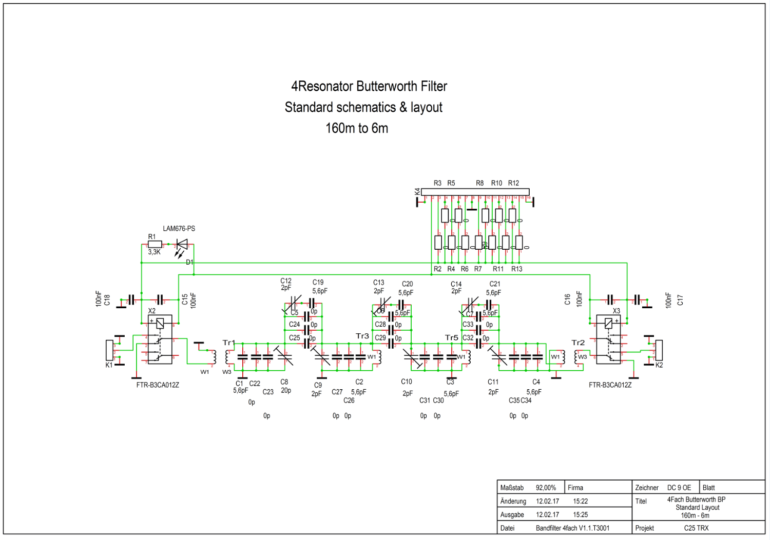
For those of you who want to build one yourself, enclosed please find the standard schematics.
I have also created an Excel sheet to calculate them; this spreadsheet is available here. A web-based version is also available here. The ones I tested and downloaded from the internet were faulty and I wasted long weeks of prototype building to find out. You can either do a Chebyshev or a Butterworth Design using the Spreadsheet.
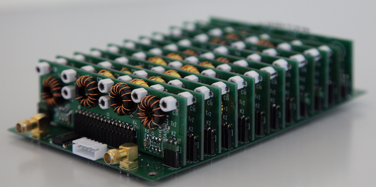
This might give you an idea how the finished filter bank looks like:
What are the benefits in using bandpass-filters in a direct sampling RX system?
The requirement to use bandpass-filters is always a subject for discussion.
As described in the excellent book by Ralf Rudersdorfer “Funkempfänger Kompendium” - ISBN 978-3-89576-224-6 - 1st Edition available at Elektor you will find on page 47 to page 52 a description of the limitations of current direct sampling receivers and the available A/D converters in a very good way.
His theoretical explanations are very much in line with our experiences while working on the Charly 25 SDR project.
His theoretical explanations are very much in line with our experiences while working on the Charly 25 SDR project.
Unfortunately this is not the case, at least not above a certain frequency.
The reason is the high noise level and the poor resolution of currently available A/D converters and the requirement to add pre-amplifiers to reach a reasonable overall system noise figure.
And by the way, the remarks below are made towards Red Pitaya / STEMlab. The same is true for all other direct sampling systems which are currently available (limitation is the A/D converter and there is only a limited selection available on the market).
The standard Red Pitaya / STEMlab
First of all it is important to understand that the standard Red Pitaya / STEMlab does include analog buffers in front of the A/D converter which can be overloaded.
Especially with the usage of the famous 1:9 to 1:16 up transformer, the Red Pitaya / STEMlab will show massive overload effects on a large broadband antenna.
We experienced this effect on a broadband dipole 25m above the ground.
By using the standard Charly 25 TRX board and only switching in 6dB of attenuation we could receive signals without artifacts.
This 6dB attenuator added to the already limited sensitivity of our RX and by listening to a station from North America the difference was obvious.
The Charly 25 TRX board has some extra connectors to enable an easy integration of bandpass-filters.
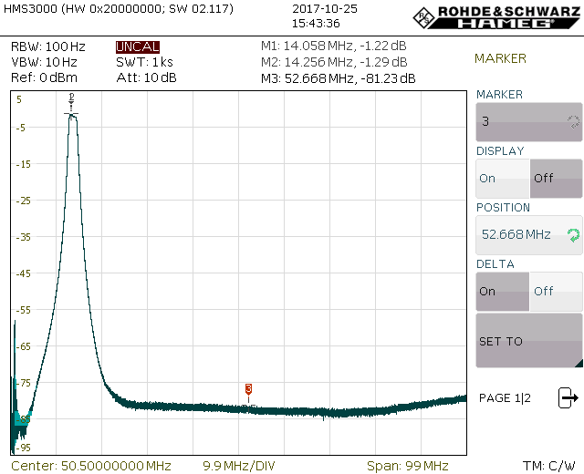
By putting in a very sharp 20m prototype bandpass-filter with 80dB far off attenuation, this problem was gone completely. We were able to use the pre amplifier of our Charly 25 TRX board with up to 36dB of gain and experienced no distortions or artifacts.
The receiver sensitivity was only limited by the antenna noise.
Filter curve of the used bandpass:
The modified Red Pitaya / STEMlab
Red Pitaya modified one board for us and left out all the analog parts.
Without all the analog parts (except the transformers) in front of the A/D converter the system cannot be overloaded easily on the antenna.
For further details please have a look at our video from the SDR Academy 2017.
Any band between the low kHz and about 14 MHz can be received without limitations. The performance is close to what people expect from this RX concept.
Receiver noise
Depending on where you live the outside noise received by the antenna is the main limitation to receiver sensitivity on lower amateur radio bands.
However, as frequency increases, the atmospheric noise becomes less of a factor and the main limitation switches towards receiver noise.
The detailed description in the book mentioned above says that the A/D noise level is well above 30dB. This is good enough on the lower bands but does not make a good and sensitive RX on higher frequencies.
A common agreement on required RX noise level is about 10 to 12dB for a good HF receiver.
For this reason pre-amplifiers are used on higher frequencies and our Charly 25 TRX board has two of them with about 16 to 18dB of gain each.
So we added some analog parts to our RX chain and for this reason it is important to understand what their impact is.
Assuming you want to work on 6m, you would need a massively reduced noise level of your RX and hence you would either use one or two amplifiers, the resulting gain would be around 32dB.
During the day this might work if you are lucky and your antenna is very selective, limited to one band only.
If working on 10m with a broad band antenna, this will certainly not work. The reason for this is that your pre-amplifier does not only amplify the 10m band, but because it is a broadband amplifier, it would also amplify everything below the 10m band.
Especially during the evening, antenna levels from broadcast stations will be -20dBm or worse. These signals would clearly overload the A/D converter. The pre-amp might overload as well. But this is not so much of a concern in the Charly 25 TRX board because if needed the MMIC selected can easily deliver more than 100mW.
Another problem might come from a nearby amateur radio station operating on a different band. You would not like to amplify their already strong signal to even higher levels.
All these issues can be easily solved by the use of a bandpass filter.
Band pass filter / topology and IP3 issues
Topology
Building a good filter is not as easy as it sounds.
The main issues are bad selectivity and very poor far off attenuation.
Ulrich Graf, DK4SX, wrote an excellent article in CQDL magazine 8/2011 about this subject. The filter above is an expanded 4-stage version of his proposed PI-filter based topology.
The filter bank we demonstrated at HamRadio fair 2017 and in CQDL magazine 9/2017 article were based on a 4-resonator Chebyshev topology. The performance was very good but did not match the performance of the prototype demonstrated above.
In addition it is very cumbersome to adjust.
For anyone interested, we made an Excel spreadsheet available for the Chebyshev design (further up on this web page).
The pi filter topology was not designed through Excel calculations but by simulations with ELSIE (the 4-stage design requires the professional version of ELSIE). It was optimized so that it can be built with 1% parts with no further adjustment.
IP3
As more analog components are added to our RX, care has to be taken about IP3 performance. The limiting factor is the core used for the coils. To our experience, T50 type Amidon cores offer a reasonable compromise between cost, size and performance. A lot of articles were written on this subject and the cores used offer an IP3 of about 35 to 37dBm.
A better performance is possible if bigger cores are used. We have not tested the impact of the NP0 ceramic capacitors on the IP3.
To reach the ultimate performance, T68 or T80 cores and MICA capacitors would probably offer the perfect solution.
This might provide a reasonable explanation on why bandpass filters are needed if you want to use the full capabilities of your direct sampling RX.
Work on a new filter bank based on the pi filter topology described above is under way.
By the way, the “official” STEMlab SDR application already includes the software modifications required to switch 12 bandpass-filters in line with the RX frequency selected.